Logic Level Circuit Wiring Diagram Level Logic Circuit Mosfe
Circuit logic probe indicator level circuits simple homemade tester build diagram Bidirectional converter logic channel level cara menggunakan Logical guessing game circuit – electronic projects circuits
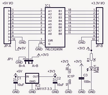
LOGIC_LEVEL_CONVERTER - Basic_Circuit - Circuit Diagram - SeekIC.com
Cara menggunakan 8 channel bidirectional logic level converter txs0108 How to use a logic level shifter/converter Logic level converter with half voltage
Logic electronics levels sparkfun learn visit
Behind the pin: logic level outputsLogic 3v converter 5v gadgetronicx voltage Electronic project: bidirectional logic level converter circuitAlt text.
Pin on arduinoHelp with i2c for a project. Logic voltage 8v 3v thresholds outputs hackaday ttl component 01s indicate esp inputsLevel logic converter i2c schematic voltages high conversion arduino different side stack gemerkt von.

Logic level converter circuit
Level logic circuit mosfet shifting raspberry pi converter bi directional arduino sparkfun guide diy learn savedLogic level test circuit diagram What is a logic level converter module?Using the logic level converter.
Logic level conversion for servos – valuable tech notesLogic circuit generator from truth table Logical guessing circuits eleccircuitLogic levels.

Sump-pump circuit – basic motor control
Logic levels ttl level 5v voltage active low sparkfun input high standard splitter p1 ongoing project output maximum considered stillReservoir circuit motor opentextbc Logic wiringLogic level converter.
Logic boolean xyz circuits expressionsLogic levels ttl sparkfun logikai textbook 0v volts circuits Logic level indicator circuitHow to use a logic level shifter circuit for components with different.

Logic levels
Logic level conversion. different voltages on high sideLevel logic converter circuit bidirectional shifter schematic ic electronic project Logic level converterTsx0108e.
Reservoir circuit – basic motor controlLogic level circuit wiring diagram Logic_level_converterSimplified logic-level circuit schematic of the in-channel digital.

Level logic converter wiring diagram
Level converter logic circuit ic converters seekic levels commonly 8v frequency 6v converts test equipment digital used some otherCircuit test logic level diagram seekic Make logic circuits for following boolean expressions:(x'y'z)+(xyzLogic level shifting.
Arduino level converter logic using esp8266 sparkfun serial uno electric convert retired module example working not cloudfront fritzing two noteArduino converter anslagstavla välj logic Level shifter circuit logic different 5v custom low voltages components use maker proLogic levels.

Wiring your first logic circuit and getting it to work
Sump circuit pump control diagram motor tank basicLevel logic arduino use shifter converter raspberry pi i2c circuit shifting tutorial photon particle I2c adxl345 logic sparkfun directional bidirectional rx webpage conectionLogic-level schematics for three logic brick designs..
.


